How to Choose the Right SPD Lightning Arrester?
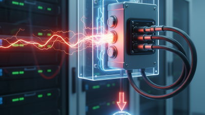
Choosing the right Spd Lightning Arrester begins with understanding the threat, not simply selecting the highest voltage rating. Lightning can heat surrounding air to approximately 30,000°C, according to the U.S. National Oceanic and Atmospheric Administration. Its current path can also exceed 200,000 amperes. These figures explain why a small, poorly matched device can fail quickly.
The practical decision starts with the electrical system. Confirm the nominal voltage, earthing arrangement, prospective short-circuit current, and installation location. IEC 61643-11 separates surge protective devices into Type 1, Type 2, and Type 3 applications. Type 1 devices address partial lightning current at service entrances. Type 2 devices protect distribution boards. Type 3 devices serve sensitive equipment nearby. IEEE C62.41.1 and IEEE C62.41.2 further describe surge environments and testing assumptions for low-voltage AC systems.
Look beyond the label.
A reliable Spd Lightning Arrester should provide suitable maximum continuous operating voltage, discharge-current capacity, voltage-protection level, and short-circuit protection. UL 1449 also emphasizes tested performance and safe failure behavior for surge protective devices used in North America. Manufacturer test reports matter, but field conditions matter more. Long cable runs, poor bonding, and shared grounding paths can increase residual voltage at equipment terminals.
No selection guide is perfect. Real installations often reveal missing details. A rooftop photovoltaic system, a hospital control panel, and a small workshop face very different exposure levels. Review the latest IEC, IEEE, or UL requirements with a qualified electrical professional. The cheapest arrester may protect nothing when coordination, wiring length, and replacement indication are ignored.
Understanding SPD Lightning Arrester Functions and Protection Levels
How to Choose the Right SPD Lightning Arrester?
An SPD lightning arrester limits transient overvoltage before it reaches sensitive equipment. Its protection level matters more than its appearance. According to the 2023 Vaisala Annual Lightning Report, more than 4.7 billion lightning events occurred worldwide. Definitions vary, but the exposure is clearly substantial.
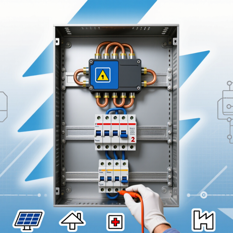
IEC 61643-11 identifies Type 1 SPDs for partial direct lightning currents. Type 2 devices handle induced lightning and switching surges. Type 3 units provide fine protection near electronic loads.
The Up value shows the residual voltage passed downstream. Choose an Up value below the equipment’s impulse withstand level. Also check Uc, Iimp, In, and Imax.
A high discharge-current rating alone does not guarantee better protection. Short connecting conductors are critical. Every extra bend adds inductive voltage.
Tips:
Match the SPD to the earthing system, service entrance, and expected surge environment. Install Type 1 at exposed main incomers, Type 2 in distribution boards, and Type 3 beside fragile equipment when coordination allows. A certified electrician should verify backup protection and disconnection requirements. Field experience shows that poor bonding can weaken a correctly rated arrester. I once saw a low-Up device perform poorly because its leads were too long. The specification was right. The installation was not. Recheck assumptions, especially where overhead lines, rooftop equipment, or long cable runs exist.
Identifying System Voltage, Current, and Earthing Requirements
How to Choose the Right SPD Lightning Arrester?
Identifying system voltage, current, and earthing requirements starts with the installation, not the product label. Measure the system’s maximum operating voltage and confirm the earthing arrangement: TN, TT, or IT. The SPD’s maximum continuous operating voltage, Uc, must exceed the highest expected voltage between live conductors and earth. A small mismatch can cause nuisance disconnection or premature failure.
Current ratings need careful interpretation. Load current is not surge current. Check nominal discharge current, In, maximum discharge current, Imax, and the short-circuit withstand rating. For higher exposure, IEC 61643-11 and IEC 60364 guidance support stronger coordination between Type 1, Type 2, and Type 3 protection. The U.S. Energy Information Administration reported that weather caused about 83% of major power outages from 2000 to 2021. That figure is not a direct lightning statistic, but it shows why transient protection deserves practical attention.
Earthing often decides whether an SPD performs well. Keep protective conductors short, straight, and well bonded. Long bends add inductive voltage during a fast surge. In TT systems, verify residual-current-device coordination; in IT systems, confirm insulation-monitoring requirements. I have seen installations with impressive current ratings fail because the earth path was poorly routed. Ratings alone are not protection. Cable length, backup protection, and separation from sensitive circuits still require review. Some site assumptions will be wrong. Test them before energizing.
Selecting the Right Arrester Type and Discharge Capacity
How to Choose the Right SPD Lightning Arrester?
Selecting the Right Arrester Type and Discharge Capacity
The installation point determines the correct SPD arrester type. In practical inspections, I first identify the building’s lightning exposure and earthing arrangement. Type 1 SPDs suit service entrances where direct lightning current may enter. Type 2 SPDs protect distribution boards from induced surges and switching events. Type 3 SPDs sit near sensitive equipment, such as control panels or network devices. Layered protection is often more reliable. Do not select one unit blindly.
Discharge capacity must match the expected surge, not just the equipment price. For Type 1 devices, compare Iimp using the 10/350 μs waveform. For Type 2 devices, check In and Imax using the 8/20 μs waveform. A higher number is not automatically safer. The SPD must also have suitable Uc and a low enough Up for the connected equipment. Incorrect voltage selection can cause premature failure.
I also verify coordination between upstream and downstream SPDs. Cable length, backup protection, conductor routing, and bonding all affect performance. IEC 61643-11 provides a useful reference for low-voltage AC SPDs. For photovoltaic, data, or control circuits, use the applicable product standard. I once treated discharge capacity as the main decision factor. That view was incomplete. Real protection depends on type, location, wiring, and tested ratings working together.
How to Choose the Right SPD Lightning Arrester?
Selecting the Right Arrester Type and Discharge Capacity
How to read the chart: Type 1 SPDs are tested with the high-energy 10/350 μs impulse and are selected by impulse current (Iimp). Type 2 SPDs use the 8/20 μs current waveform and are commonly specified by nominal discharge current (In). Type 3 SPDs are installed close to sensitive equipment and are commonly evaluated with a combination-wave test, typically using a 1.2/50 μs open-circuit voltage and an 8/20 μs short-circuit current.
The values shown are representative reference points used in technical selection discussions, not universal minimum ratings or product specifications. The final choice should consider the installation’s lightning exposure, earthing system, prospective short-circuit current, required voltage protection level (Up), coordination with upstream and downstream SPDs, and applicable IEC 61643-11 requirements.
Checking Installation Location, Wiring, and Coordination
Choosing the right SPD lightning arrester starts with its installation location. Place it near the service entrance or distribution board, where surge current enters the building. Keep the path short and direct. IEC 60364 guidance commonly targets about 0.5 metres for total connecting conductor length. Long bends create extra inductive voltage during a surge. That detail is often missed.
Wiring quality matters as much as the arrester rating. Use correctly sized conductors, secure terminals, and a low-impedance protective earth. Avoid sharp loops. Separate power and signal routes where practical. NOAA reports roughly eight million lightning strikes worldwide each day, so occasional surge exposure is not a rare design event. It is a normal risk. Still, SPD protection cannot correct poor earthing or damaged insulation.
Coordination requires checking every protection stage. A service-entry Type 1 or Type 2 SPD should match the system voltage, earthing arrangement, short-circuit rating, and backup protection. Downstream Type 3 devices need suitable upstream coordination and close placement near sensitive equipment. IEC 61643-11 provides testing requirements for low-voltage SPDs. NFPA’s Electrical Fires report estimated 32,650 U.S. home fires annually involved electrical distribution and lighting equipment from 2015 to 2019. That figure does not prove an SPD prevents fires, but it supports careful installation. A neat panel can still hide weak coordination. Review the actual conductor route, not only the specification sheet.
Verifying Standards, Certification, and Maintenance Needs
Choosing the right SPD lightning arrester requires more than comparing voltage ratings. Verify which standard applies to the installation. IEC 61643-11 is widely used for low-voltage surge protective devices. UL 1449 may apply in other markets. Always confirm current local requirements. Check the test report, product classification, discharge current, voltage protection level, and short-circuit rating. A certificate alone is not enough. It should match the exact model and configuration being installed.
Certification marks can appear reassuring, but details matter. Ask for traceable documentation from an accredited testing body. Confirm whether the device protects power circuits, data lines, or both. Inspect the installation instructions before purchase. Incorrect earthing, excessive lead length, or poor coordination can reduce protection. Even experienced teams can miss these points during a rushed installation. That deserves a second look.
Tips: Record the installation date and device specifications. Inspect the status indicator after severe storms, switching events, or power faults. Replace the SPD when its indicator shows failure, after significant damage, or according to the manufacturer’s service guidance. Check terminals for heat marks, looseness, corrosion, and moisture. Keep inspection records with the electrical maintenance log. Testing is useful, but it cannot replace visual checks and correct grounding. Maintenance intervals should reflect exposure, building risk, and local electrical rules. Some assumptions will be wrong, so review them after every major system change.

 +86 13868429846
 Contact Phone
 Contact Email