Leave Your Message

What Is a Digital Current Protector and How Does It Work?

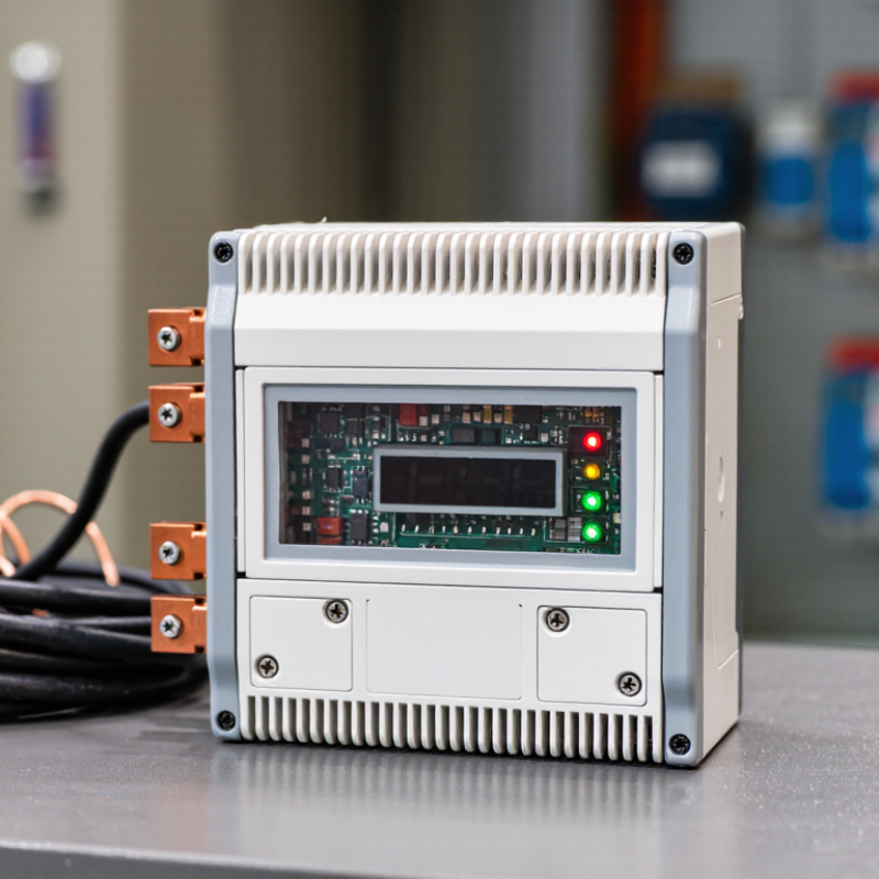
A Digital Current Protector is an electronic safety device that monitors electrical current and responds when the load becomes unsafe. Unlike a simple fuse, it can measure changing conditions continuously. It may detect overloads, short circuits, stalled motors, or abnormal current patterns. Then, it can disconnect the circuit through a relay, semiconductor switch, or contactor.

Inside the device, a current sensor measures the flow through the conductor. A microcontroller compares that reading with programmed limits. If the current rises above a safe value, the protector reacts within a defined time. A small display may show amperage, trip status, temperature, or fault information. Some models also store events or communicate with an industrial control system.

In a workshop, this response can prevent a warm cable from becoming a damaged cable. In a control cabinet, it can help protect motors, power supplies, and sensitive electronics. The device does not remove every electrical hazard. Correct wiring, grounding, enclosure design, and professional testing remain essential. Installation should follow the manufacturer’s instructions and applicable electrical standards.

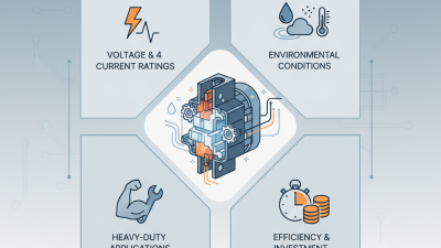
Performance depends on sensor accuracy, response time, ambient temperature, and correct configuration. A setting that is too low may cause nuisance trips. A setting that is too high may delay protection. That balance deserves careful attention. In practice, engineers should review the equipment’s rated current, starting current, and expected operating conditions before selecting a Digital Current Protector. Some product claims also require verification through datasheets and independent certification. The technology is useful, but it is not magic.
What Is a Digital Current Protector and How Does It Work?

Definition and Role of a Digital Current Protector in Electrical Systems

A digital current protector is an electronic device that monitors current flowing through an electrical circuit. Its role is to detect abnormal conditions and help prevent damage to connected equipment. A sensor measures the current, while internal circuitry compares the reading with configured limits. If current rises above a set threshold, the protector can trigger an alarm or disconnect the circuit. Some models also detect unusually low current, which may indicate a failed motor or broken connection.

Unlike a basic fuse, a digital protector can show readings and fault information on a small screen. An electrician can use these details to identify whether a pump, compressor, or other load is drawing too much current. Response time and protection features vary by device, so settings must match the equipment and wiring. A display is useful, but it does not guarantee correct protection. Poorly chosen limits can cause nuisance trips or leave equipment exposed.

Tips: Check the device’s current rating and settings against the equipment specifications. Keep the display accessible, and record normal operating readings for comparison. Have a qualified electrician install and test the protector. Real systems can behave unpredictably, so review settings after equipment changes.
Core Components: Sensors, A/D Converters, and Microprocessor-Based Relays

What Is a Digital Current Protector and How Does It Work?

A digital current protector detects abnormal current and signals a breaker to disconnect a circuit. Its sensor, often a current transformer or Hall-effect device, converts current into a smaller measurable signal. The analog-to-digital converter samples that signal and turns it into numbers. Small errors matter. Sensor saturation, electrical noise, or poor calibration can distort those numbers. The microprocessor-based relay calculates values such as RMS current and compares them with configured thresholds and time delays. If a limit is exceeded, it sends a trip command to the breaker. Fast, but not magic.

The relay’s settings determine how it responds: an instantaneous threshold may handle a severe fault, while a time-delay curve can allow brief startup surges. Engineers should coordinate these settings with downstream equipment and verify them through testing. EPRI’s 2001 report, The Cost of Power Disturbances to Industrial & Digital Economy Companies, estimated annual U.S. costs of $104–164 billion. That historical estimate covers power disturbances broadly; it is not a measure of protector performance. Still, it shows why dependable monitoring matters.

Tips: Check sensor range, wiring polarity, and trip settings during commissioning. Compare recorded current with a calibrated instrument. A tidy display can still hide a bad assumption.

How Current Sampling and Threshold Settings Detect Overloads at 50/60 Hz

A digital current protector samples the waveform from a current sensor, then estimates current over a defined window. IEC 60038:2009 identifies 50 Hz and 60 Hz as standard supply frequencies: one cycle lasts 20 milliseconds at 50 Hz, or about 16.7 milliseconds at 60 Hz. That timing matters. A 64-sample-per-cycle design, for example, takes about 312 microseconds between samples at 50 Hz and 260 microseconds at 60 Hz.

The processor calculates an RMS value or another configured current measure and compares it with a pickup threshold. If current exceeds that setting, the protector applies its delay or trip curve rather than reacting to every brief spike. IEC 60255-151:2013 describes functional and timing requirements for overcurrent protection. In practice, settings must account for normal startup surges, sensor accuracy, and the equipment being protected. A threshold set too low can cause nuisance trips; too high can leave an overload undetected.

For instance, a motor starting near its rated current may briefly draw several times that value. The protector’s sampling window and delay determine whether it treats this as a transient or a sustained overload. Not instantly. Wiring noise, distorted waveforms, and sensor drift can still affect readings, so commissioning tests matter. A neat calculation is not a substitute for checking actual load behavior.

Protection Sequence: ANSI 50 Instantaneous and ANSI 51 Time-Overcurrent Functions

A digital current protector measures feeder current through current transformers and compares it with configured limits. ANSI 50 is the instantaneous overcurrent function. When current exceeds its pickup setting, it sends a trip command with no intentional delay. The circuit breaker still needs time to open, so “instantaneous” does not mean zero clearing time. This function is often used for high-current faults near protected equipment.

ANSI 51 responds to overcurrent using a set time-current curve or delay. With an inverse-time curve, higher current usually produces a shorter operating time. This allows a downstream device time to clear a nearby fault before an upstream protector trips. A fault near the feeder’s far end may produce less current, so the 51 function can provide useful backup. Settings depend on load, transformer ratios, fault levels, and coordination with other devices.

These functions often monitor current in parallel; they are not always a neat two-step sequence. If current exceeds the 50 threshold, that element may trip before the 51 timer expires. If it does not, the 51 function can operate after its measured delay. That distinction matters. Engineers should verify pickup values and timing against the actual installation, then review trip records or perform suitable tests. A setting that looks reasonable on paper can still need adjustment in service.

Testing and Performance: IEC 60255 Requirements for Measuring Relays

A digital current protector measures line current and trips when it detects a configured fault. Its display may show a pickup value, but a bench test reveals whether the device responds at the right current and time.

IEC 60255-1:2017 sets common requirements for measuring relays and protection equipment. IEC 60255-151:2009 addresses overcurrent protection functions and their operating characteristics. These standards guide tests; they do not impose one universal pickup setting for every installation.

A practical test injects calibrated current through the relay’s input, then records pickup current, reset behavior, and operating time in milliseconds. Engineers compare those readings with the device’s declared characteristics and applicable IEC tolerances.

Test points should cover both sides of the set threshold, not just the expected trip point. Small errors matter. A relay that trips late may leave equipment exposed; one that trips too readily can interrupt service.

Record the test instrument’s calibration status, wiring, ambient conditions, and each measured result. The IEC documents define a framework, but site conditions still shape performance. A clean bench result is not the whole story, and test records can miss details when setup notes are thin.