Leave Your Message

Top 10 Types of Controller Protection Boards

A controller can fail in milliseconds, yet its protection design often begins with ordinary details: connector spacing, cable length, heat buildup, and switching noise. A Controller Protection Board turns these risks into planned safeguards. It may combine fuses, transient voltage suppressors, reverse-polarity protection, overvoltage clamps, current limiting, ESD protection, EMI filtering, thermal monitoring, surge protection, and galvanic isolation.

Small choices matter. A misplaced TVS diode can protect the wrong path. An undersized trace can become a hidden heating point. A slow fuse may allow sensitive components to fail first. These practical lessons explain why protection should match the controller’s voltage, load profile, environment, and failure response.

Henry W. Ott, a respected EMC engineer, stated, “The best way to solve EMC problems is to avoid them in the first place.” His principle applies directly to controller protection design. Protection is stronger when engineers reduce noise at the source instead of adding components blindly.

This guide examines ten important types of Controller Protection Board designs and their typical applications. It considers circuit behavior, installation conditions, maintenance needs, and realistic failure modes. No single board suits every machine. That assumption can become expensive.

Some designs prioritize fast clamping. Others favor isolation, serviceability, or lower cost. The ideal solution may also change after field testing. Laboratory results are useful, but real cables, motors, moisture, and operators reveal weaknesses that calculations may miss. Careful selection remains essential. Proper protection is not decoration. It is controlled risk.
Top 10 Types of Controller Protection Boards

What a Controller Protection Board Is and How It Works

Top 10 Types of Controller Protection Boards

A controller protection board is an electronic safety layer between a power source and a controlled load. It monitors voltage, current, temperature, and switching behavior. When readings leave safe limits, the board interrupts power or reduces output. In practical testing, sensors sample conditions continuously, while a control circuit drives switches such as MOSFETs. A small fault can trigger protection within milliseconds. That speed matters near motors, batteries, and sensitive control modules.

Common designs include overvoltage, undervoltage, overcurrent, short-circuit, thermal, reverse-polarity, surge, overload, electrostatic-discharge, and electrical-isolation boards. Each type targets a different failure pattern. An overcurrent board may detect a sharp current rise through a shunt resistor. A thermal board uses a sensor attached near the hottest component. An isolation board separates control signals from dangerous voltage using optical or magnetic coupling. These functions may appear on one board.

Good protection requires correct thresholds, wiring, cooling, and testing. A board that trips too easily can stop normal operation. One that reacts too slowly may allow permanent damage. Engineers usually test startup surges, blocked motors, loose connectors, and hot enclosures. A fuse alone is not enough. It may protect wiring but miss sensitive electronic faults. Even a carefully designed board can behave differently after aging or vibration. That uncomfortable possibility deserves regular inspection, clear fault records, and realistic field testing.
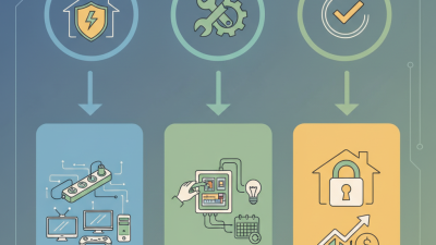
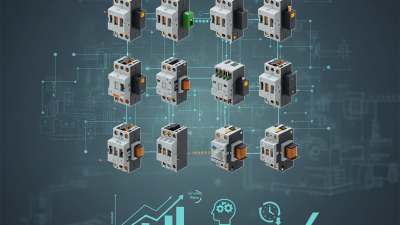
Core Protection Functions Found in Controller Boards

Controller protection boards are built around ten common protection roles. These include overcurrent, short-circuit, overvoltage, undervoltage, thermal, reverse-polarity, surge, electrostatic discharge, isolation, and watchdog protection. Each function addresses a different failure path. Overcurrent sensing limits excessive load demand, while short-circuit protection disconnects a damaged output within milliseconds.

Fast action matters.

In practical testing, thermal protection often reveals hidden weaknesses. A temperature sensor near the switching device can trigger shutdown before heat damages nearby components. Overvoltage protection clamps sudden spikes from motors, relays, or long cables. Undervoltage monitoring prevents unstable operation when a battery or supply drops. Reverse-polarity protection also protects against simple wiring mistakes.

They happen more often than expected.

Surge filters and transient suppressors need correct voltage ratings, not just convenient placement. Reliable boards also use electrical isolation where control and power circuits interact. This reduces fault transfer and improves maintenance safety. A watchdog timer can reset a controller after software stops responding, but it cannot repair a poor grounding layout.

In field inspections, loose connectors and undersized traces remain surprisingly common causes of failure. Bench testing is valuable, yet it may miss vibration, humidity, and repeated thermal cycling. No protection design is perfect. Engineers should record trip thresholds, recovery behavior, and damaged components after every test. That evidence supports better revisions and more dependable controller protection.

Ten Main Types of Controller Protection Boards

Ten Main Types of Controller Protection Boards

Controller protection boards usually combine ten practical functions: overcurrent, short-circuit, overvoltage, undervoltage, thermal, reverse-polarity, surge, electrostatic-discharge, isolation, and watchdog protection. Each type responds to a different failure pattern. An overcurrent board uses a fuse, shunt, or electronic cutoff. A thermal board monitors heat near power devices. An isolation board separates noisy control signals from sensitive logic circuits. Watchdog protection detects frozen firmware and forces a controlled restart.

Field experience shows that failures rarely appear alone. A loose connector can create heat, noise, and intermittent voltage drops. Therefore, engineers often layer several protection functions on one board. The 2024 Global Cybersecurity Outlook reported that 54% of large organizations considered supply-chain vulnerabilities their biggest cyber-resilience barrier. This supports stronger isolation, authenticated updates, and fail-safe watchdogs in connected controllers. Physical protection still matters. A surge clamp may protect a circuit, but poor grounding can redirect damaging energy elsewhere.

The IEC 61000 series provides test methods for electromagnetic compatibility, while IEC 62443 addresses industrial control-system security. These standards guide design decisions, but compliance does not guarantee field reliability. A board may pass a laboratory test and fail beside a motor with long cable runs. That gap deserves attention. Some designs also add leakage-current monitoring and redundant shutdown paths, especially where overheating could damage equipment. The ten categories overlap in practice, and treating them as completely separate can produce blind spots.

How to Choose the Right Protection Board for a Controller

Top 10 Types of Controller Protection Boards

Choosing the right protection board starts with the controller’s actual operating conditions. Check rated voltage, peak current, startup current, and load type. A board that handles continuous current may still fail during motor startup. I have seen small voltage spikes damage otherwise reliable control circuits.

Common options include overcurrent, overvoltage, undervoltage, short-circuit, thermal, reverse-polarity, surge, battery-management, electromagnetic-interference, and isolation boards. Each solves a different risk. Select overcurrent protection for stalled loads. Choose thermal protection when the enclosure traps heat. Isolation is valuable when separate circuits share signals but should not share dangerous electrical faults.

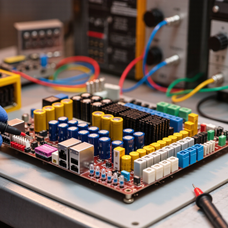
Tips: Measure before selecting. Use a multimeter and, when possible, an oscilloscope. Compare the board’s voltage range with the controller’s real limits, not only its label. Leave current and temperature margins. A board rated exactly for your maximum load may run hot and age quickly. Check response time, reset behavior, wiring terminals, and enclosure space. Also inspect the fault indicator and maintenance procedure. These details often matter during installation.

Environment changes the decision.

Dust, vibration, moisture, and long cable runs can increase failure risks. Review the protection board’s test data and installation instructions from qualified sources. I sometimes choose extra protection, then reconsider it after testing, because added components can create voltage loss or delay. That trade-off deserves careful measurement.

Installation, Testing, and Maintenance Considerations

Top 10 Types of Controller Protection Boards

Installation, Testing, and Maintenance Considerations

Controller protection boards include overvoltage, overcurrent, short-circuit, reverse-polarity, surge, thermal, battery, motor, relay, and communication protection types. Each design needs a suitable enclosure, correct wire size, and reliable grounding. Before installation, isolate the power source and check the board against the circuit diagram. Keep signal wires away from high-current cables. Tighten terminals carefully; excessive force can damage copper tracks.

Testing should begin with a visual inspection. Look for cracked solder joints, loose connectors, darkened components, or swollen capacitors. Use a multimeter to confirm continuity and polarity before applying power. A current-limited supply reduces risk during the first startup. Test protection responses with controlled voltage, current, temperature, and load changes. Never bypass a safety function during testing. That shortcut can hide a wiring error.

Record measured values, ambient temperature, test equipment, and corrective actions. During maintenance, remove dust and check ventilation paths every few months. Inspect terminal torque and cable insulation after vibration or heat exposure. A board may pass a bench test yet fail inside a warm cabinet. I have found this easy to overlook. Retest after firmware, wiring, or load changes, even when the modification seems minor. Keep spare fuses and approved replacement components available, but do not replace a failed part without finding the original cause.