+86 13868429846
Leave Your Message
-
Contact WhatsApp
-
 Contact Phone
-
 Contact Email
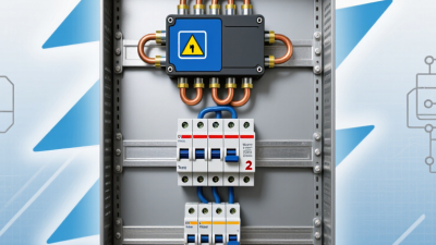
An Spd Lightning Arrester protects electrical equipment from sudden voltage surges. These surges may come from nearby lightning, utility switching, or faults on the power network. Unlike a fuse, it does not mainly interrupt continuous overcurrent. It reacts to a brief rise in voltage and redirects dangerous energy toward the grounding system.
Inside many devices, metal oxide varistors provide the main protective path. Under normal voltage, they remain highly resistant. During a surge, their resistance drops sharply. This action limits the voltage reaching sensitive equipment, such as circuit boards, LED drivers, routers, and industrial controllers. The response happens within microseconds. Fast enough.
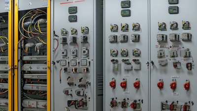
Installation quality matters as much as the arrester itself. Short, straight conductors reduce unwanted inductive voltage. A loose terminal, poor bonding point, or long grounding wire can weaken protection. In real panels, neat wiring is not merely attractive; it can influence surge performance. I have seen protection plans fail because the device was correctly selected but badly connected.
A reliable Spd Lightning Arrester should match the system voltage, earthing arrangement, exposure level, and expected discharge current. Professional selection should also consider Type 1, Type 2, or Type 3 classification, depending on the installation location. Relevant IEC or UL requirements can support safer evaluation, but labels alone do not guarantee complete protection. No surge device is magic. It may degrade after repeated events, so its status indicator and replacement guidance deserve regular attention. This article explains how the device works, where it belongs, and which practical details should not be overlooked.
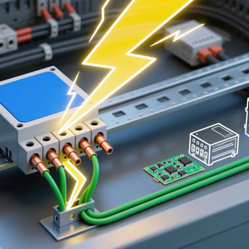
What Is an SPD Lightning Arrester and How Does It Work?
An SPD lightning arrester limits transient overvoltage before it reaches sensitive equipment. It diverts surge current through a protective path, usually toward earth. The device remains nearly non-conductive during normal voltage. During a surge, its voltage-dependent components respond within microseconds. Fast action matters.
IEC 61643-11 classifies low-voltage SPDs by their test duty and installation position. Type 1 SPDs face high-energy partial lightning currents, tested with a 10/350 μs waveform. They suit service entrances where a structural lightning protection system may exist. Type 2 SPDs use the 8/20 μs current waveform and commonly protect distribution boards. Type 3 SPDs use a combined 1.2/50 μs voltage and 8/20 μs current test. They are installed close to sensitive loads, such as control panels or computers.
The numbers are important. A higher discharge-current rating does not automatically mean better protection. Coordination between upstream and downstream SPDs also matters. IEC 61643-11 specifies performance tests for residual voltage, temporary overvoltage, and short-circuit behavior. Installation quality remains decisive.
Industry risk data reinforces the need for layered protection. The National Lightning Safety Council reports that lightning remains a recurring cause of electrical damage and service disruption in the United States. Vaisala’s Annual Lightning Report also records hundreds of millions of lightning events globally each year. These reports describe exposure, not guaranteed equipment failure. Real sites are less predictable. Even a correctly selected SPD can underperform if cable lengths, grounding, or backup protection are poorly considered.
| Data Dimension | Technical Information | Practical Significance |
|---|---|---|
| Definition | A Surge Protective Device (SPD) is a device designed to limit transient overvoltages and divert surge current to earth or another suitable conductive path. | It helps protect electrical and electronic equipment from lightning-induced surges and switching transients. |
| Operating Principle | Under normal voltage, the SPD presents a high impedance. During a surge, its voltage-limiting or voltage-switching component conducts and provides a low-impedance discharge path. | The surge is diverted away from sensitive loads, and the residual voltage is reduced to a safer level. |
| Common Internal Technology | Metal-oxide varistors (MOVs) are voltage-limiting components. Gas discharge tubes (GDTs) are voltage-switching components. Some SPDs combine multiple technologies. | Component selection affects response, leakage current, follow current, energy capability, and residual voltage. |
| IEC 61643-11 Classification | IEC 61643-11 classifies low-voltage AC SPDs by their test duties as Type 1, Type 2, and Type 3. | The type indicates the intended installation position and the surge waveform used for testing; it is not a universal ranking of product quality. |
| Type 1 SPD | Tested with a partial lightning current impulse, commonly represented by the 10/350 μs waveform. Its principal discharge-current parameter is Iimp. | Typically installed at the origin of an installation where a direct lightning-current contribution is possible, such as at the main incoming distribution point. |
| Type 2 SPD | Tested with an 8/20 μs current impulse. Important current parameters include nominal discharge current In and maximum discharge current Imax. | Commonly installed in main or sub-distribution boards to discharge induced lightning surges and switching transients. |
| Type 3 SPD | Tested with a combination wave, typically consisting of a 1.2/50 μs open-circuit voltage waveform and an 8/20 μs short-circuit current waveform. | Installed close to sensitive equipment as fine protection. It is normally used downstream of Type 1 or Type 2 protection. |
| Maximum Continuous Operating Voltage (Uc) | The maximum RMS voltage that may be continuously applied to the SPD protection mode without causing unacceptable deterioration. | The selected Uc must be suitable for the system voltage, earthing arrangement, and expected temporary overvoltages. |
| Voltage Protection Level (Up) | The declared maximum voltage at the SPD terminals under specified test conditions. | Up should be coordinated with the impulse withstand level of the equipment being protected. |
| Nominal Discharge Current (In) | The peak value of an 8/20 μs current impulse used for the operating-duty test of an SPD, particularly for Type 2 applications. | A higher In generally indicates greater tested discharge capability, but installation conditions and coordination must also be considered. |
| Maximum Discharge Current (Imax) | The maximum peak value of an 8/20 μs current impulse that the SPD can discharge at least once under the specified test conditions. | It provides information about the SPD's maximum surge-current withstand capability, but it should not be used alone to select an SPD. |
| Lightning Impulse Current (Iimp) | The peak value of a current impulse with a 10/350 μs waveform used for Type 1 testing. | It represents the SPD's declared capability to handle the relevant partial lightning-current duty. |
| Temporary Overvoltage (TOV) | A temporary power-frequency overvoltage that can result from faults, neutral displacement, or other network conditions. | An SPD must have suitable TOV behavior so that a temporary system overvoltage does not cause unsafe failure. |
| Backup Overcurrent Protection | An upstream fuse or circuit breaker may be required when specified by the SPD manufacturer or installation standard. | It limits power-frequency fault current if the SPD reaches the end of its service life or develops an internal fault. |
| Status Indication | Many SPDs include a visual or remote indication showing whether the protection module remains operational. | The indicator supports inspection and maintenance, but it does not replace electrical testing or periodic system checks. |
| Installation Coordination | Protection is improved by coordinating SPD types, keeping connecting conductors short and straight, and bonding the protective earthing system effectively. | Poor lead routing or excessive conductor length can increase the voltage appearing at the protected equipment. |
| Note: The applicable edition of IEC 61643-11, local wiring regulations, system earthing arrangement, prospective short-circuit current, and the equipment's impulse withstand level should be verified before selecting and installing an SPD. Electrical installation work should be performed by qualified personnel. | ||